
Fascia Signs and Diagrams
This page shows how signs and diagrams on the layout fascia help our operators
know where they are on the railroad and also where they are headed next.
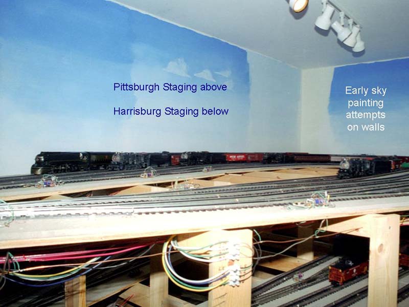
| The Pennsylvania & Western is a large model railroad. The main room is 52 feet long and 28 feet wide (not counting the 10x12 extension that houses Horseshoe Curve. The design is point to point, with the main staging yards in an adjacent 8x18 room at the lower left of the plan. The mainline run is 550 feet (5 scale miles), spiraling three times around the room on the trip between staging yards. A branch line leaves the Main Line at Gap Junction and ends in a three-track staging yard under Horseshoe Curve. |

|
| In the staging room, there are two double-ended yards. The upper yard represents Pittsburgh, Conway Yard and Shire Oaks Yard. It has six tracks that loop around the room (trains on these tracks can be re-used during an operating session) and two shorter stub tracks. |
|
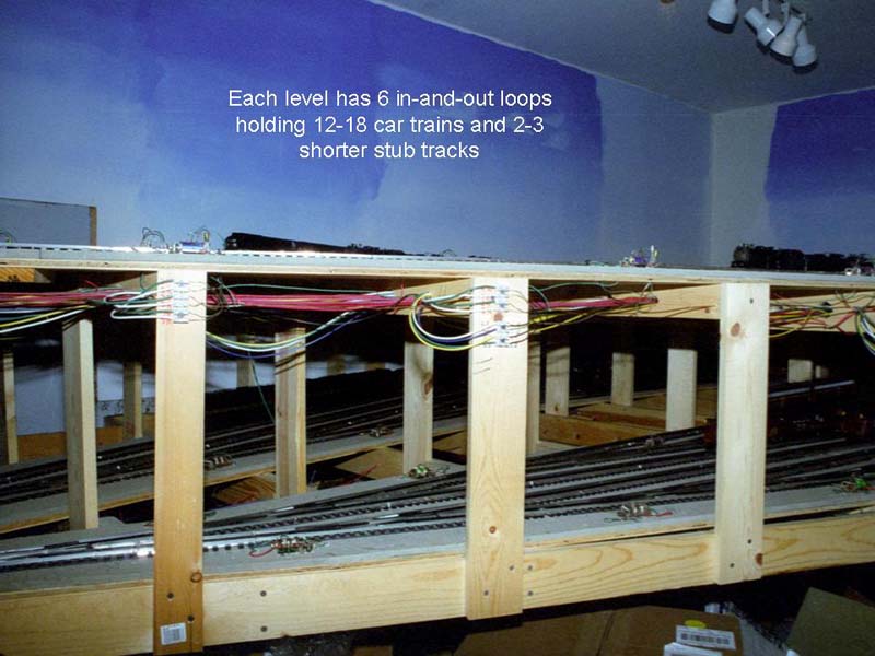
| Harrisburg, Enola Yard and Petersburg Branch staging is located 16 inches below Pittsburgh staging. This yard also contains six double-ended loop tracks and also has three shorter stub tracks. |
|
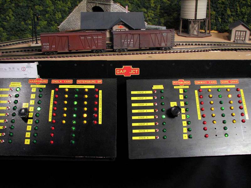
| These are the staging control panels located in the main layout room. The Gap Jct sign on the fascia is for the town of Gap Junction which sits above the panels. Town locations are all shown in PRR-style red and gold station signs. The multiple locations represented by the staging yards are all shown on the appropriate panel. |
|
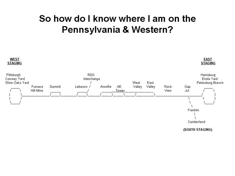
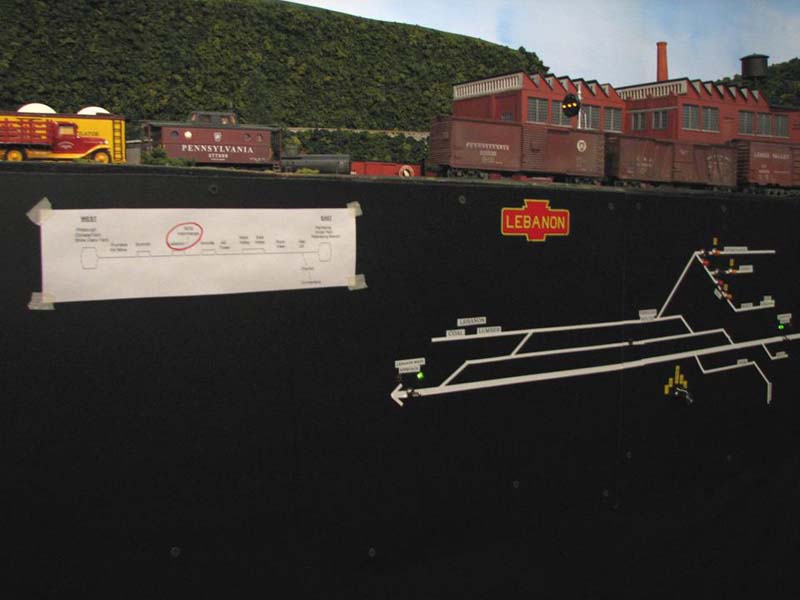
| Here is the schematic diagram of the Pennsylvania & Western mainline. It shows all of the towns in order from East to West. The distances between towns are not shown to scale. For example, it is about a scale mile from West Valley to Annville but only one third of a scale mile from Annville to Lebanon. |
|
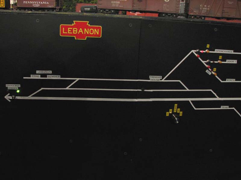
| At every town, the name of the town is shown using a station sign on the fascia and a copy of the schematic is also posted with the town name circled in red. An operator thus knows at a glance where he/she is and which towns lie to the East and West of here. Finally, a track diagram of the town is also lined onto the fascia. |
|
| The track diagram shows the name and location of each industry that has rail service. Pushbuttons to operate switch machines and magnetic uncouplers are also incorporated into the diagram. Diagrams are made using white automotive pinstripe tape (3/16" wide for the Mainline and 1/8" wide for all other tracks). |
|
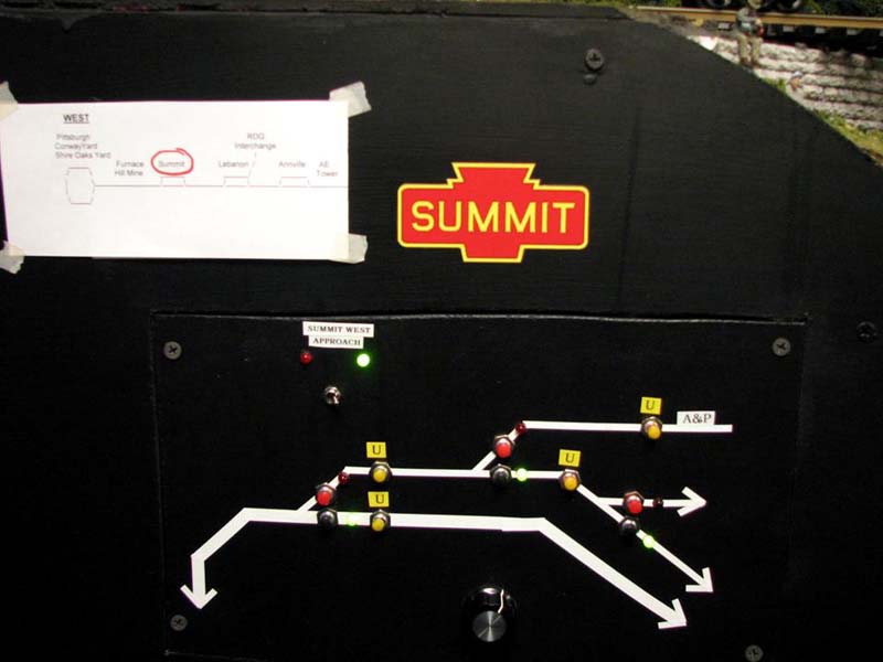
| This view of the panel at the West end of the town of Summit shows the fascia information: town name sign, schematic with town name circled in red, track diagram, pushbuttons for switch machines and magnetic uncouplers (those marked with a "U"). A toggle switch to set the West Approach Signal is also shown. Train crews switching at Summit under dispatcher authority throw the toggle to set a mainline approach signal to the stop indication. |
|